FarmIT 3000 - Agrident ASR550 Static Reader.
Our Static Reader of Choice
Agrident produce a range of EID Readers designed for use in a static roll, that is not in the hand but designed to read an EID tag and send the tag number to something else, either weigh head or computer via a RS232 cable or bluetooth connection. Although agrident provide the readers fully package we decided a long time ago to purchase the electronic boards from Agrident then provide our own enclosures, connectors and wiring. We made that decision because we believed Farmers need 'big plugs for big hands' and things that if they have to they can fixed with minimal tools.
So we provide the ASR550 EID reader packaged in a slightly more farmer friendly manor and fixable as far as possible on farm.

The Reader Module
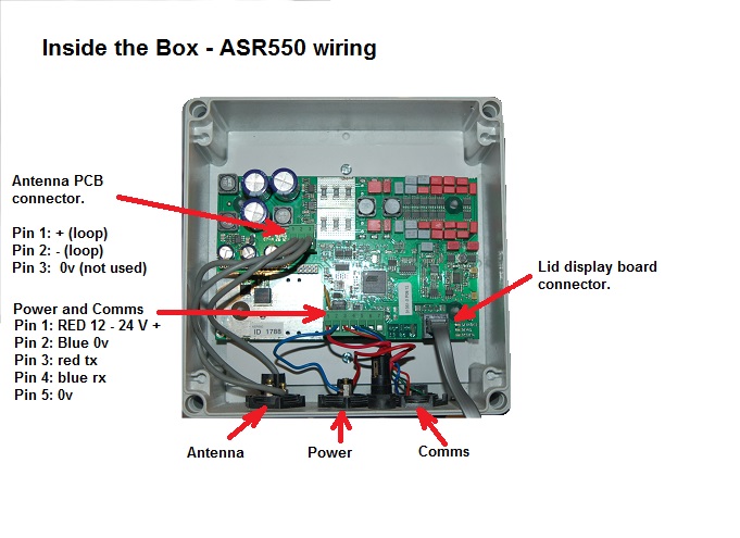
The reader comprises a single electronic board enclosed in an IP67 waterproof box. It has three external connectors, power, antenna and output to computer/weighhead. Internally a connector also connects the board to the LED lights on the inside of the box lid. The connections to the 3 sockets are all 'screw' terminals and can be connected or disconnected with a small 3mm blade screwdriver.
Operation
Operation is very simple, as the reader simply reads the EID tag and outputs the EID via the comms port. The unit self tunes to the antenna upon switch on. The three lights indicating, Power (amber), EID Tag Reader (Green) and Error (Red)
POWER - 12dc - 24dc
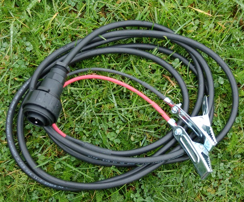
The ASR550 board will run on a DC supply voltage from 12V to 24V, normally we run the unit off a 12v DC battery for example a leisure battery, but a car battery will work. The power connector has only 2 pins and is the center plug. The unit can be powered from a mains power supply but care should be taken to ensure that the DC supply has NO RIPPLE. A ripple can interfer with the EID tag read. We supply a specific power supply which we have used for many years.
Communications
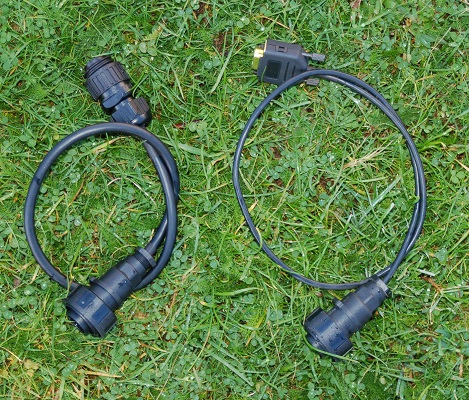
The ASR550 unit is designed to communicate with the weigh head or computer via RS232 serial communications. It does this via 3 wires , Transmitt, Receive and Earth. The right hand socket has four pins but only actually uses 3. Again all wires have screw terminal connections. The leads shown ae short 30 - 40cm as we have the ASR550 mounted next to the Weigh head. Left is the XR5000 lead, right the XR3000 lead.
Antenna
The antenna (inductive loop) is nothing more than a loop of copper wire. The connector has 3 terminals and three wires but one is not used. The actual antenna is made up of a single wire which 'loops' a number of turns, different size antenna have different numbers of turns and are fine tuned by mal tunning capacitors ( normally on asmall board). In our case most of our antenna are built into the actuall weigh crate, or in a plastic panel or aluminium frame.
Bluetooth
Although we do not generally fit bluetooth to the ASR550, we can but again prefer to set a simple bluetooth adapter, rather than the manufactured one. This is down to flexiablity and cost. All our unit with bluetooth have a clear plastic front panel so you can see the bluetooth mosudle and its status indicators. Although bluetooth is very good all it really does is replace the cable which of course is not really a requirement if the reader module is next to the weigh head.
Plug Sockets
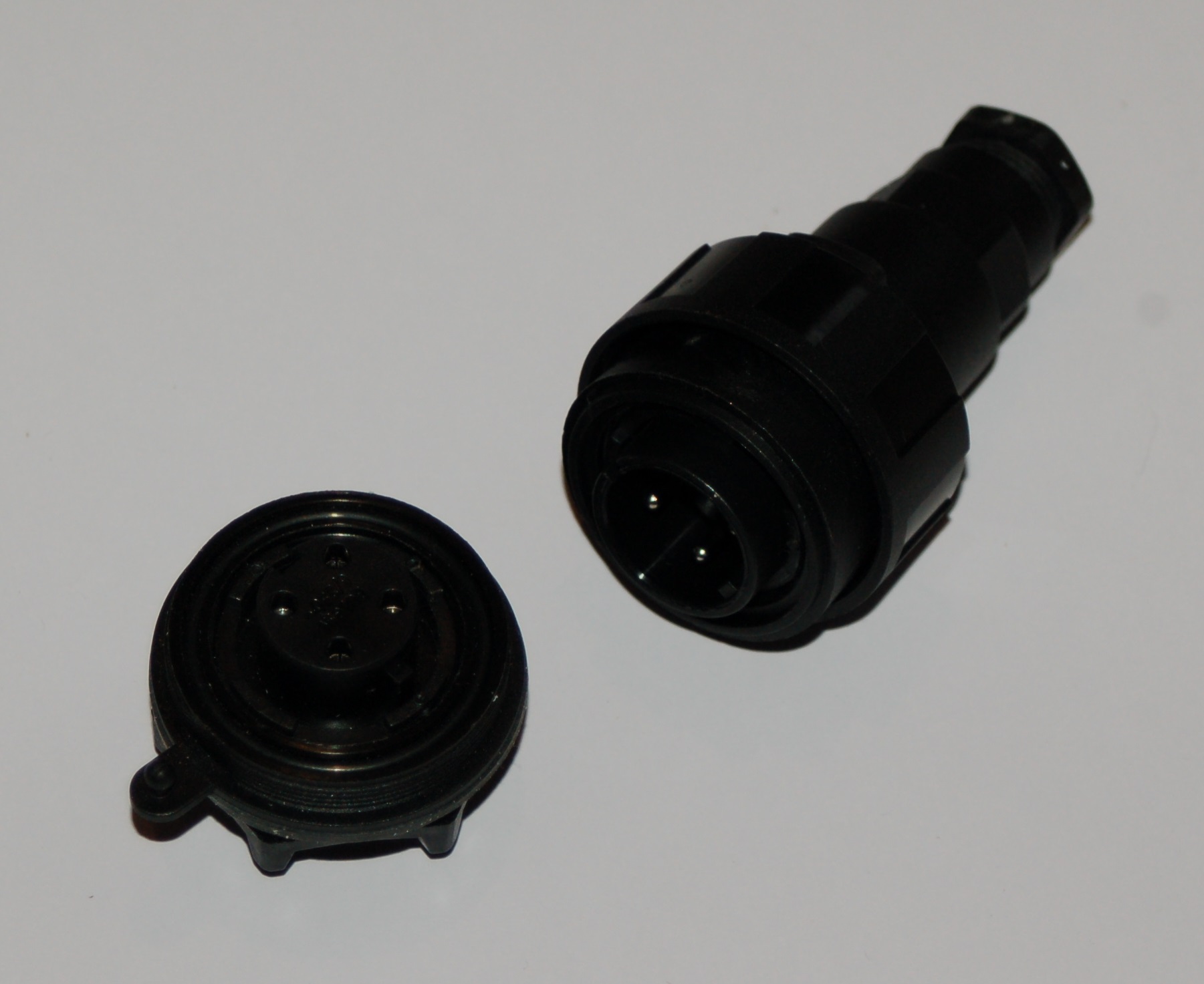
We have chosen the plug sockets because they are large making it easy for big hand to plug and unplug. They also have internal screw terminals (just like a mains plug) which means they are easily fixed if a wire gets chewed up by an animal or pull out. Although they are slightly more expensive the ability to fixe them is very usefull. They are also easily available in the UK from RS components, part numbers are below.
Inside the Box
Inside the box you will see the ASR550 board, the wiring to the plugs and fuse and the connector to the front panel LED board.
Common Faults
The ASR550 static reader is as you can see not a complicated thing. The board itself is easily replacabled, but has no servicable parts, if the baord fails you need a new board. Having said that in the last 15 years we have had only 2 board failures. Most faults are simply loose connections or broken wires. Of course using screw terminals means some come loose, but unlike soldered connections they are easily fixed. The most common of all faults is in the wires being pulled from the plug so we will look at the three pulugs and wires in detail.
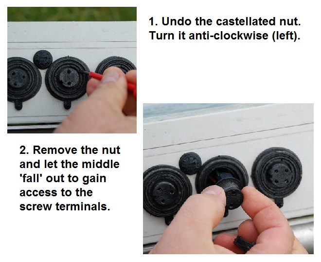
Undoing the sockets on the box
The bulgin sockets on the bottom of the reader module cable can be undone by unscrewing the castellated ring nut on the outside of the socket. Romoving the ring allows the middle of the socket to 'fall' out and give easy access to the terminals at the back of the socket.
Undoing the Plugs
The bulgin plugs all unscrew, the rear of the plug is unscrewed by the cable clamp nut, the front unscrews by removing the castellated locking ring.
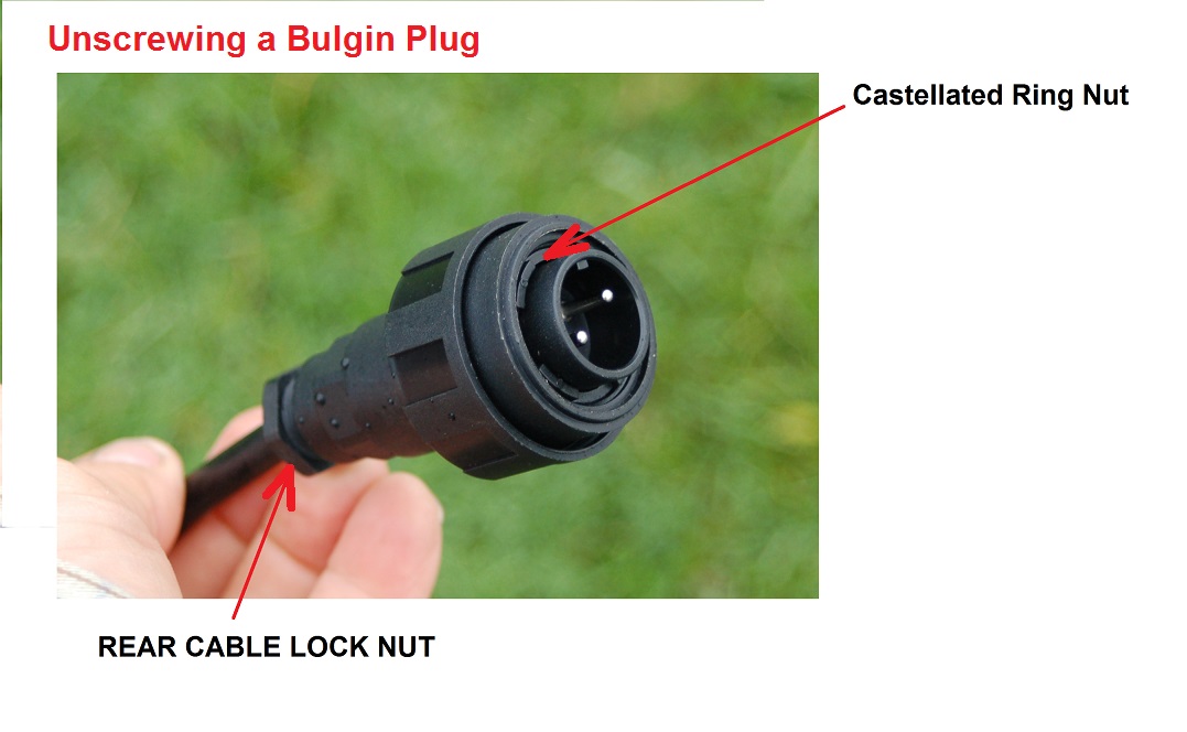
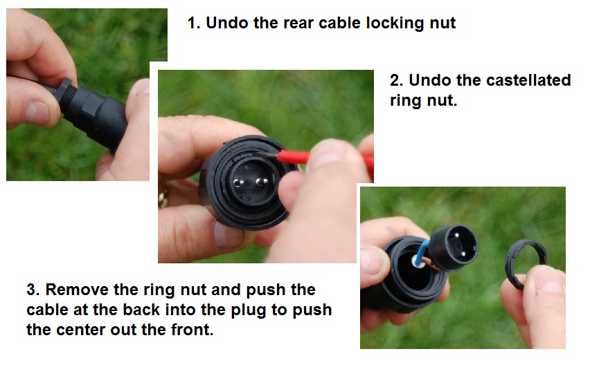
Undo the rear clamp nut, twist anticlockwise, normally we only do them up hand tight!, Next insert a small screw driver into the castellation and turn the whole ring anti clockwise (left). The plug can then be pulled apart to access the screw terminals.
Cable Wiring
Power Cable
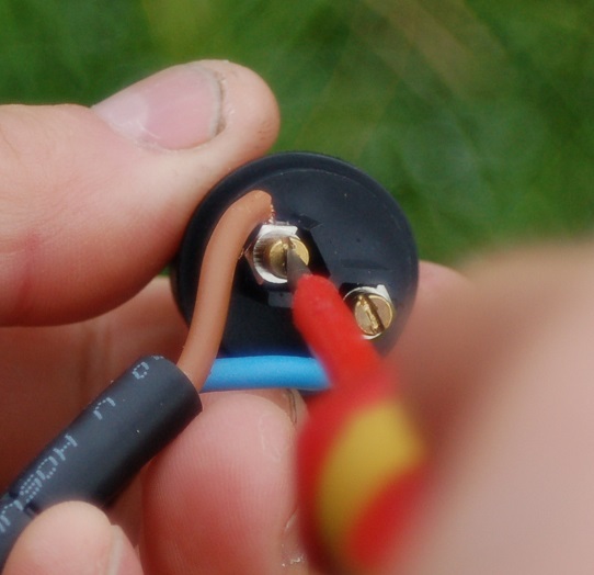
The power cable is the two pin center connector. Both socket and plug are labled (marked) L (live) and N (neutral). We wire RED (brown) for live, Blue for neutral. At the other end of the cable RED croc clip for live, blue for negative. Connecting the croc clips round the wrong way does no harm, the reader just will not work!. The live red wire is also fused inside the box. check the fuse is tightly done up and has not blown.
Communications Cable
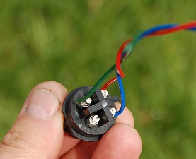
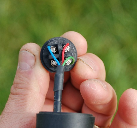
The comms cable uses the four pin right hand socket. Both socket and plug are labelled pins 1 - 4. 1 Green (0v) , 2 RED ( Transmitt ), 3 Blue ( Receive ).
Rear view of the socket ( Reader Module)
Rear view of wiring of the Plug ( Lead )
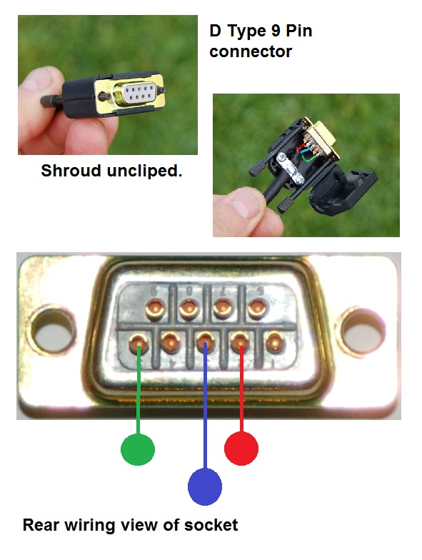
The other end of the communications cable depends on the connection to the equipment. The standard connection to a PC or the older Tru-Test XR3000 uses a Female D Type connector. They are prone to rusting and because they only accept small soldered wire easily broken. Tru-Test changed to a more robust connector for the XR5000 and EW7 range, which is must better although still a soldered connection.
D Type Comms Wiring
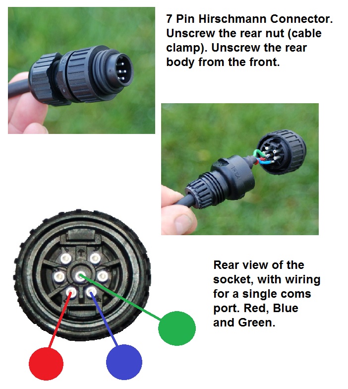
XR5000 EW7 Comms Wiring
The XR5000 and EW7 use a more substancial plug, 7 pin, it provides a common 0v line on the center pin, power to the device, and two com ports, though we only use one.
Plug and Socket Part Numbers
The plugs and sockets above are all available from UK suppliers, we use RS components and find them extreamly good. Although we are more than happy to fix your leads or supply spares below is a table of RS part number just in case you need to find it yourself.
| Description |
Type |
RS Part Number |
| Antenna Socket |
Female 3 Pin Bulgin |
483-916 |
| Antenna Plug |
Male 3 pin Bulgin |
483-922 |
| Power Socket |
Female 2 Pin Bulgin |
483-887 |
| Power Plug |
Male 2 Pin Bulgin |
483-893 |
| Comms Socket |
Female 4 Pin Bulgin |
293-5841 |
| Comms Plug |
Male 4 Pin Bulgin |
293-5857 |
| Pc \ XR3000 Comms Plug |
Female 7 Pin D Type |
472-843 |
| XR5000 \ EW7 Comms Plug |
Male 7 Pin Hirschmann |
359-4407 |